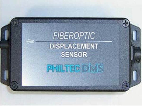
DMS Digital Fibre Optic Displacement Sensor
These sensors provide a linear distance output with RS232 or USB communication. Dynamic light signals reflected from target surfaces are converted to distances by comparing the sensor signals to gap calibration tables stored on-board the sensor. The digital sensors have the added simplicity of providing a linear output for the full operating range of the sensors.
DMS Sensor – RS232 Outputs directly to PC/PLC with a build on LCD display. Max output rate of 5208 samples/second with a possible max two channels.
mDMS Sensor – RS232 Output directly to PC/PLC with a max output rate of 5208 samples/sec
muDMS Sensor – Smallest possible sensor with USB output directly to PC/PLC and a max output rate of 16 000 samples/second.
Bluetooth for all RS232 DMS sensors
Contact Our Sales Team
Contact our sales team via email regarding this product: +44 (0)1823 333343
Email UsMake An Enquiry| Reflectance Dependent Models – Digital | |||
| Model # | Fiber Bundle Diameter (mil) | Operating Range (mm) | Far Side Resolution @ 5208 Samples/Sec µm |
| DMS-D6 | 6 | 1 | 0.4 |
| DMS-D12 | 12 | 2 | 0.4 |
| DMS-D20 | 20 | 1.3 | 0.2 |
| DMS-D21 | 21 | 2 | 0.4 |
| DMS-D47 | 47 | 5 | 1.3 |
| DMS-D63 | 63 | 3 | 0.25 |
| DMS-D64 | 64 | 6 | 0.4 |
| DMS-D100 | 100 | 10 | 0.7 |
| DMS-D125 | 125 | 15 | 0.4 |
| DMS-D169 | 169 | 19 | 1.5 |
| DMS-D170 | 170 | 30 | 2 |
| DMS-D171 | 171 | 50 | 3 |
| DMS-D240 | 240 | 76 | 2.5 |
| Reflectance Compensated Models – Digital | |||
| Model # | Fiber Bundle Area (mm) | Operating Range (mm) | Resolution @ 5208 Samples/Sec nm |
| DMS-RC19 | Ø 0.5 | 0.76 | 100 |
| DMS-RC20 | Ø 0.5 | 1.3 | 80 |
| DMS-RC25 | 0.64 x 3.2 | 0.76 | 50 |
| DMS-RC32 | Ø 0.8 | 3 | 500 |
| DMS-RC60 | Ø 1.5 | 4 | 180 |
| DMS-RC62 | 1.6 x 3.2 | 2.5 | 250 |
| DMS-RC63 | 1.6 x 3.2 | 5 | 640 |
| DMS-RC90 | 2.3 x 4.8 | 9 | 400 |
| DMS-RC100 | Ø 2.5 | 6 | 550 |
| DMS-RC171 | Ø 4.3 | 15 | 650 |
| DMS-RC190 | 4.8 x 4.8 | 25 | 650 |
| DMS-RC290 | Ø 7.4 | 35 | 2500 |
- Fibre optic principle means complete insensitivity to magnetic fields and high voltage electrical fields; can therefore be used where inductance or capacitance sensors do not work
- Rugged construction; suitable for all types of difficult environments such as vacuum, high pressure, cryogenic temperatures, high temperature, in fluids or explosive atmospheres
- Linearised output for the full operating range of the sensor
- DMS Control Software includes a data averaging filter for averaging data samples from 2 samples, (the fastest rate), to 4096 samples, (highest resolution)
- Rotor runout
- Thermal growth
- Distance of glass
- Displacement in fluids
- Actuator stroke
- Diaphragm deflection
- Read/Write head tracking
- Solenoid travel
- Measurement in vacuums in cryogenic temperatures
- Compressor blade vibration
- Shock testing
- Thread inspection
| OPTIONS FOR DIGITAL SENSORS | |||
| FOR D MODELS | FOR RC MODELS | OPTION CODE | FEATURE |
| Bluetooth – for all RS232 output sensors | |||
| √ | A | Provides analog outputs for muDMS sensors | |
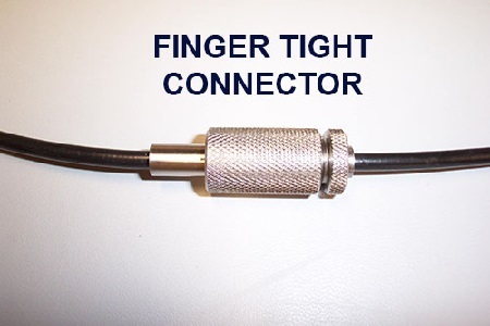
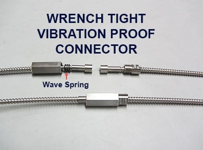
| √ | B | Connects sensor system with inline connector. (D6, n/a) *Option B is also required for use with vacuum passthru flanges & assemblies Bv2, Bv3, Bv4, BvF | |
| √ | 2B | Connects sensor system with two inline connectors. Not available for all models. | |
| √ | B1 | Connects sensor system with bulkhead connector (D6 n/a) | |
| √ | Bv1 | Connects sensor system with single channel vacuum passthru hardware for 10 E-7 torr. Includes ultra-torr compression fitting (D6 n/a) | |
| √ | Bv133 | Same as Bv1 with 1.33”diameter mini-cf type flange for bulkhead mounting | |
| N/A | Bv2 | 2 port single channel vacuum passthru flange for D models for E-11 torr (D6 n/a) *also requires option B | |
| √ | Bv3 | 3 port single channel vacuum passthru flange for RC models for E-11 torr *also requires option B | |
| √ | BvF | Connects sensor system with inline connector. (D6, n/a) *Option B is also required for use with vacuum passthru flanges & assemblies Bv2, Bv3, Bv4, (D6, RC12 & RC20 n/a) *also requires option B | |
| √ | — | Standard jacket: PVC monocoil -PVC over a steel helical winding. semi-crush-proof, liquid-tight, not autoclavable or MRI compatible. Good to 105C. | |
| √ | C1 | Jacket: stainless steel interlock, crush proof, not liquid tight. good to 850c. | |
| √ | C2 | Jacket: silicone – MRI and Bio-compatible, flexible, liquid-tight, not crush-proof. good to 200c | |
| √ | C3 | Jacket: Silicone over PTFE wrap – semi-crush-proof. good to 200c. short lengths only | |
| √ | C4 | Jacket: corrugated – all plastic. semi-crush-proof, liquid-tight, light-weight, mri compatible. Good to 85C. | |
| √ | C5 | Jacket: ptfe over stainless steel interlok – vapor Barrier, liquid-tight, crush-proof. good to 260c. | |
| √ | C51 | Jacket: ss interlok over ptfe – vapor Barrier, liquid-tight, crush-proof, poor flexibility, good to 260c. | |
| √ | C6 | Jacket: PVC over nylon wrap – semi-crush-proof, liquid-tight, emf compatible. good to 105c. | |
| √ | C7 | Jacket: ptfe tubing – autoclavable, MRI & EMF compatible, vapor barrier, liquid-tight. good to 260c. | |
| √ | C8 | Jacket: pvc – polyvinyl chloride – very flexible, liquid-tight, emf & mri compatible, not autoclavable, not crush-proof. good to 105c. | |
| √ | C9 | Jacket: annealed (semi-rigid) stainless steel tubing. liquid tight. good to 850c. | |
| √ | C10 | Jacket: silicone over ss interlok sheathing. liquid-tight, crush-proof. good to 200c. | |
| √ | C11 | Jacket: polyolefin shrink tubing – thin wall moisture/vapor Barrier, not crush-proof, poor flexibility. good TO 150C. | |
| √ | E1 | Extra length of fiberoptic cable (some models limited to 10 feet, others to 49 feet); Any fiber bundle < Ø 2.5mm | |
| √ | E2 | Extra length of fiberoptic cable (some models limited to 10 feet, others to 49 feet); Any fiber bundle < Ø 2.5mm | |
| √ | Fv1 | Low vacuum passthru for 10 e-4 torr. provides Ø 0.375” x 3”l solid section on fo cable | |
| √ | Fv2 | Low vacuum passthru for 10 e-4 torr. provides Ø 0.250” x 3”l solid section on fo cable | |
| √ | Fv3 | Low vacuum passthru for 10 e-4 torr. provides Ø 0.500” x 3”l solid section on fo cable | |
| √ | R1 | Ambient light rejection | |
| √ | R2 | Blue light sensor, 470nm | |
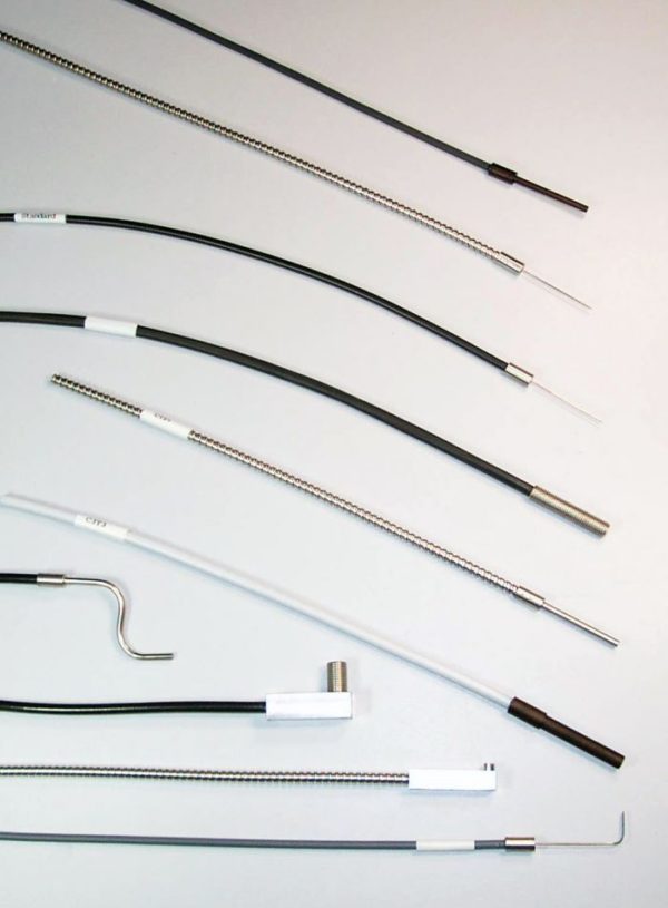
| √ | T1 | Tip: straight, customised | |
| √ | T2 | Tip: threaded | |
| √ | T3 | Tip: non-metalic, (torlon or peek) | |
| √ | T4 | Tip: 90° tubing | |
| √ | T5 | Tip: 90° square body, unthreaded end | |
| √ | T6 | Tip: 90° square body, threaded end | |
| √ | T7 | Tip: made to customer specifications | |
| √ | T8 | Tip: high temperature, 350°c max. | |
| √ | T9 | Tip: high temperature, 480°c max. | |
| √ | T10 | Tip: high temperature, >480°c (quartz fibers) | |
| √ | T11 | Tip: non-magnetic (brass or aluminium) | |
| √ | T12 | Tip: invar (low expansion coefficient) | |
| √ | W | Window: recessed sapphire epoxied into tip for high pressure or vacuum | |
| √ | Wb | Window: sapphire brazed to sensor tip for high pressure or vacuum | |